White Paper: Contactless Corridor 2.0 – Reference Design
At Future Travel Experience (FTE) 2021, Paravision presented its blueprint for the Biometric Contactless Corridor, an approach for harnessing the latest generation technology to deliver a compelling, seamless passenger experience. While imminently deployable, this proposed approach does require a significant commitment in terms of footprint, installed hardware, and personnel support. With that in mind, in this Reference Design we present the Biometric Contactless Corridor 2.0 (“CC2.0”), which builds upon the thinking and technology presented in the original Contactless Corridor while delivering both a more cost-effective implementation and coupling it with details on how to integrate with Paravision Search and other backend infrastructure. This reference design will focus on an immigration / border management use case, but many of the concepts would carry over to other touch points in air travel such as pre-board screening (“security”) or boarding.
Introduction
The air travel industry has had a long-standing goal of delivering a truly seamless passenger experience, where travelers can walk into a terminal, through security, through immigration, and onto an airplane without waiting in line, showing a ticket or identity document, or even pulling a personal device out of their pocket or bag. However, each of these checkpoints requires positive confirmation of identity, which historically was only feasible with either manual or automated review of identity documents (which is stationary by nature) or a stationary biometric check at a kiosk, counter, or eGate. Recent developments in AI, advanced camera technologies, and latest-generation computing have enabled new thinking and new options in travel: high quality biometric identity from people in motion are now not only feasible, but practical and cost-effective.
Glossary
Advanced Passenger Information System (“APIS”) – System for providing traveler information to border management and related agencies in advance of arrival. APIS facilitates the population of day-of-travel databases which are at the core of the Contactless Corridor’s functionality.
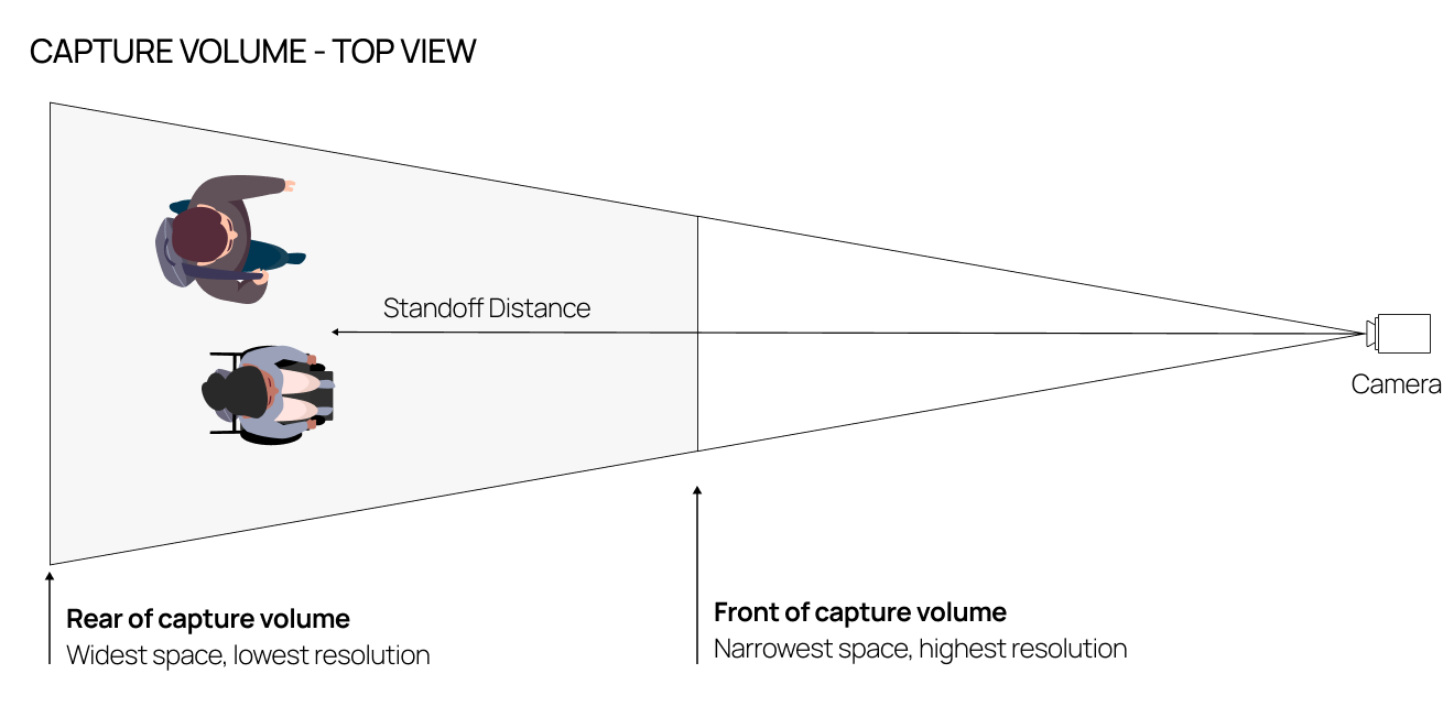
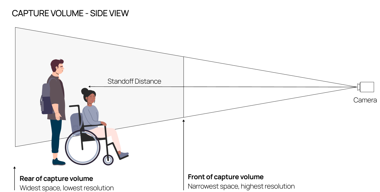
Capture Volume – The physical space defining where a camera system will be functionally capable of capturing high quality biometric images. A capture volume is virtual – not defined by physical objects, but rather the combination of optics, imaging configuration, and biometric image quality requirements.
Contactless Corridor – A solution for seamless (touchless, on-the-move) next-generation travel experiences. Facilitated by an opt-in biometric database, the Contactless Corridor uses face recognition to enable automated identity checks, decreasing queues and improving the travel experience.
Contactless Corridor 2.0 (“CC2.0”) – A solution for seamless next-generation travel experiences that builds upon the concepts introduced in the original Contactless Corridor in a way that can be deployed more cost-effectively and better in-line with a conventional physical layout and security management approach.
Paravision Search – Paravision’s elastic, cloud-ready, enterprise-grade face recognition engine. See here for more detail.
Paravision Streaming Container – Paravision’s Docker-based software solution for detecting faces and capturing high-quality biometric images from streaming (e.g. RTSP) video.
Standoff Distance – The physical distance from a camera to an individual. See here for more detail.
Traveler Verification System (“TVS”) – A backend software system (typically run by a customs and border management agency) which handles biometric opt-in, day-of-travel data, biometric matching, and interfacing with higher level customs and border management applications.
Review of The Original Contactless Corridor
As originally presented, the Contactless Corridor relies on four key building blocks:
- Remote registration, which enables travelers to securely register their identity and opt-in to the biometric program from the comfort of home. In the two years since the concept was briefed at FTE, mobile registration and identity verification have become thoroughly mainstream for a range of digital services, making this step easier than ever.

- Clear signage, integrating mobile apps and physical messaging, supporting biometric opt-in while making the travel experience less confusing and more intuitive.
- The Contactless Corridor itself, which travelers can simply walk through without stopping, waiting in line, or worrying about cumbersome ticket or device handling. The contactless corridor is made possible through a combination of ceiling-mounted high definition cameras which are capable of delivering high-performance face recognition from a distance, and from travelers in motion.
- Expert support staff, including security officers overlooking the environment and reviewing biometric results as well as customer-facing agents who can help travelers who do not match against the authorized travel list.
With CC2.0, we retain various aspects of the technology implementation and traveler experience while aiming to reduce cost, complexity, and confusion.
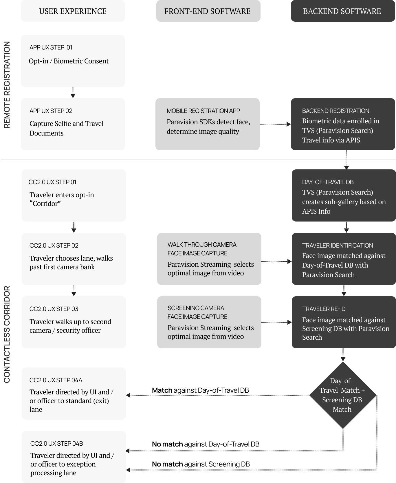
Contactless Corridor 2.0 Floorplan, Passenger Flow, and Concept of Operations
Whereas the original Contactless Corridor was defined by a wide open space and a large array of cameras, CC2.0 takes a more structured approach:

- Travelers enter the opt-in “Corridor”, which is reduced from the open environment in the original Contactless Corridor to a more basic array of stanchions and parallel single-person pathways which in turn facilitate more linear flow.
- Travelers walk past a row of overhead cameras (a.k.a. “Walkthrough cameras”). Depending on the implementation, it may be desirable to integrate attention mechanisms so that the travelers specifically look up at the cameras, which can optimize biometric image quality. However, the cameras can also be located such that a shallow angle is feasible and travelers can simply walk past without worrying about where they are looking.
- The overhead cameras capture video from the travelers, and are integrated with Paravision Streaming containers to parse and extract the highest quality image for each passenger.
- The highest quality image is compared with the day-of-travel database for opted-in travelers. Here, we refer to this database and the backend system that serves it as a “Traveler Verification Service (TVS),” a term conventionally used by US CBP for this type of biometric passenger facilitation. The biometric matching portion of this TVS can be fully served by Paravision Search.
- Passengers then walk up to a more conventional counter with a front-facing camera (a.k.a. “Screening camera”) mounted on it. Passenger photos are again captured, either using Paravision Streaming or Paravision SDKs.
- Photos from the screening camera are compared with those captured from the walkthrough cameras in step 3 to determine the identity of the passenger. The identity is then linked to travel authorization as determined by the TVS.
- If passengers are approved by the TVS system then they are waved through by the security officer at the counter.
- If passengers are not approved, then they are sent to the exception handling lane.
It is worth highlighting the need for two databases and two biometric matches in this process. Why not just match once and direct the traveler to the correct lane?
The first match is key in terms of determining if the traveler is authorized to pass. However, even in a fast system where the database is properly filtered to handle only day-of-travel records, the delay of reaching back to a centralized system could be 1-2 seconds. This is easily absorbed as a person is walking through an area of a couple meters (given a brisk walking speed of 1.5 meters per second) but would be enough of a delay that it could introduce stoppage and confusion if it were happening at a single checkpoint.
Introducing a second checkpoint gives the traveler a few meters to walk, thereby giving the system sufficient time to perform matching without any delay that would require that traveler to stop. The purpose of the second match is to ensure that the person walking past the security officer at any given time matches a record returned from the TVS. It is performed against a very small database (only those people who have passed the first checkpoint but not the second) and so can happen locally and in essentially real-time. In this way, and in summary:
- As the traveler passes from the first camera to the second, the TVS has time to check all passengers against the day-of-travel database to determine if passage is authorized.
- The local match provides real-time feedback to both the security officer and the traveler who is passing by the officer.
- The response from the second match can be displayed in a clear and intuitive way, directing travelers who do not successfully match to the exception handling lane.
- Given the parallel lane organizational structure, only one traveler passes by a security officer at a time, allowing for fully control of the operational environment.
Contactless Corridor 2.0 Benefits
- High throughput, seamless travel – Enabled by the two-camera, two-match approach, most travelers will not experience any perceived delay, simply walking through the environment and only slowing as they pass the security officer to be waved in one direction or another.
- Full operational control – Enabled by single-traveler-per-lane layout, each traveler passes by a security officer who can make controlled decisions and in the worst case pause traveler flow.
- Integration with standard TVS system architectures – Leveraging day-of-travel database matching, high performance camera systems, and advanced AI computing, the system is able to deliver optimal biometric performance from travelers in motion.
- Options for staged deployment – Given the single-lane traveler user experience, it is possible to roll out CC2.0 in a lane-by-lane manner, enabling POC, pilot, and structured production rollout without major disruption to the physical environment.
System Architecture
The CC2.0 system architecture carries over naturally from the Concept of Operations described in the last section. Key system architecture components include software available from Paravision (typically at the core technology level), application software (typically operated by the airline, airport, or government agency), and hardware endpoints (such as cameras or local processors).
Here, registration data originates from two key points:
- The visitor registration app, similar to the embodiment from the original Contactless Corridor “remote registration” function. This is both the method for enrolling high quality biometric data as well as managing biometric consent / opt-in. The visitor registration app would most typically be considered a native iOS or Android application which would use Paravision SDKs for face detection, image quality analysis, and user feedback. While registration could work using a simple static selfie image with acceptability measured on the backend system, integration of automated capture and real-time user feedback can dramatically enhance the overall capture experience, improving biometric image quality while reducing the need for retries. High quality biometric registration is at the core of an overall successful implementation and should not be short-changed.
- Airline Advanced Passenger Information System (APIS), which informs the customs and immigration application (and therefore the TVS) of which passengers will be traveling on a given day. This is a critical step as it enables the creation of a day-of-travel database. The day-of-travel database is a key concept in that it cleaves what could be a multi-million record database of all registered passengers down into something which is more typically thousands or tens of thousands of records. This reduction in database size increases speed, improves accuracy, and decreases compute costs.
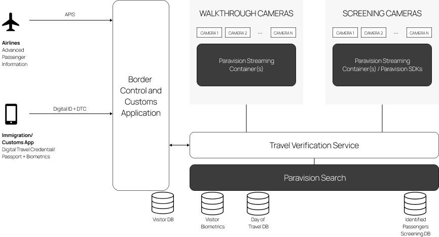
The overall customs and border management application will take the biometric registration and APIS data and either enroll the biometric data in the TVS or inform the TVS of who will be traveling on a given day. The TVS in turn provides this direction to Paravision Search, which is the biometric matching workhorse for CC2.0. Paravision Search is not a hosted cloud service, but rather a cloud-ready platform which is deployed fully within (or alongside) a given TVS in a trusted computing environment. Paravision Search enables several key functions:
- Biometric registration – Paravision Search has responsibility for maintaining a database of biometric templates for all enrolled travelers.
- Day-of-travel database creation – Utilizing the information passed from the APIS to the TVS, Paravision Search will dynamically create sub-galleries aligned with who will be traveling on a given day.
- Day-of-travel matching – With data collected from the “Walkthrough” cameras, Paravision Search performs high-speed matching against the day-of-travel database.
- Identified traveler matching – Paravision Search maintains a parallel database of travelers identified at the walkthrough cameras, delivering real-time results from the second (“Screening”) cameras. This can be done within the same instance of Paravision Search used for day-of-travel matching, or a separate instance located on-site or on the backend.
Face images are extracted from the walkthrough cameras using the Paravision Streaming Container. Paravision Streaming Container includes face detection, face tracking, and face image quality analysis:
- Face detection finds all of the faces in the field of view.
- Face tracking creates a single ID for any face seen so that a single face image can be provided for matching. Without tracking, Paravision Search would be asked to match faces over and over again, as typically a camera will capture multiple frames of a given person walking by. Paravision Streaming Container uses sophisticated tracking that is AI based to improve consistency, while also providing tracking across multiple cameras. In this way, if one person is seen across two cameras, the system can treat them as a single ID and submit a single image for matching.
- Face image quality analysis looks at the biometric quality of every frame of every face. The system can therefore optimize the submitted biometric image quality, submitting the single best frame from a given track.
Paravision Streaming Container is most typically implemented with RTSP, a standard approach for streaming video from networked cameras. Given the typical positioning and integration of the walkthrough cameras, networked IP cameras are recommended for CC2.0. More information on these cameras is provided in the Hardware Recommendations section of this reference design.
The screening cameras can use the same streaming video approach as the walkthrough cameras. However, given the positioning near the security officer and integration with a traveler-facing UI, it may be more desirable to use a USB-controlled camera. In that case, rather than the Streaming Container (which is optimized for RTSP feed), the Paravision SDK may be more useful. The SDK can be used on Windows or Linux applications and deployed with standard desktop PCs or NVIDIA Jetson edge processors. Once again, the output of the SDK (or Streaming Container) will be a single, optimized face per passenger that is passed to the Identified Passenger DB within Paravision Search.
Imaging Design and Hardware Recommendations for Biometric Contactless Corridor
High-Level Considerations
By design, Paravision face recognition is not reliant on the use of a specific camera technology, sensor resolution, or optical configuration. To the contrary, it will work well with any standard RGB camera as long as the optical image quality is sufficiently high. The key constraints come into the size of the face with regard to the overall field of view as well as the resolution of the face itself. For Paravision’s standard face detector, implementations should conform to the following:
- Relative size of face: Faces (as measured by the width x height of the bounding box) should be greater than 0.3% of the overall field of view. So, for example, with a 1080p camera (2,073,600 pixels total), the face area should be greater than 2,073,600 * 0.003 = 6221 pixels. In this case, a face of 80 x 80 pixels (6400 total) would meet this requirement.
- Absolute size of face: Face width should be larger than 50 pixels (full face width, not interpupillary distance) at a minimum and larger than 100 pixels to achieve optimal matching accuracy.
The specifics of the camera system to be deployed are based on a combination of the physical configuration and sensor resolution. A 720p, 1080p, or 4K camera does not determine inherently that the system will deliver high-performance face recognition. Rather, a combination of the sensor resolution, camera orientation (i.e. portrait vs. landscape), optical field of view, and lens focal length will then determine the standoff distance (distance from camera to traveler) as well as the horizontal and vertical fields of view at those standoff distances.
Lighting and environmental conditions are key considerations as well. There is no hard-and-fast rule there, as there is an interplay between lighting, camera technology, UX, and other factors. However, generally speaking, keeping lighting as uniform and diffuse as possible, avoiding backlighting and side-lighting, and achieving consistency of lighting through a 24 hour period will all promote optimal biometric performance.
Capture Volume Design and Camera Placement
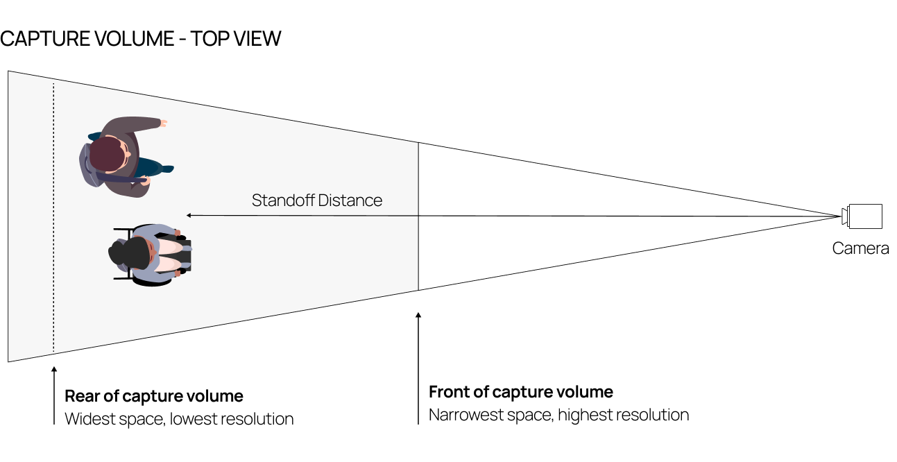
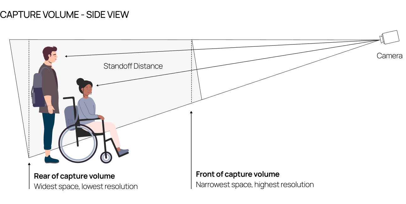
The result of the above considerations will typically be a trapezoidal capture volume that is smaller at the front of the volume and larger at the rear. The size at the rear of the volume will be limited by the minimum acceptable face resolution (e.g. 100 pixels across the face at >0.3% of the total field of view), whereas the size at the front of the volume will be limited by the minimum acceptable horizontal and vertical field of view. In many cases, the horizontal field of view will be dictated by the desired user experience and camera placement, whereas the vertical field of view will be dictated by accessibility requirements such as the Americans with Disabilities Act (ADA).
In this document, we will not present a dimensioned geometry for the layout of cameras, as deployed physical environments may vary greatly. However, the following sketches should help CC2.0 implementation partners to define potential design approaches given their physical location. A few notes:
- Here, we are showing two sample configurations: overhead camera placement and straight-ahead camera placement.
- In the overhead camera configuration, the camera is placed above the traveler height (presumably from a ceiling or gantry mounting) and positioned downward to face the traveler. Designs should aim to minimize the angle between the camera axis and the shortest, closest face in the field of view. This overhead configuration may be most effective for the walkthrough cameras.
- In the straight-ahead camera configuration, the camera is placed at or near eye height and positioned straight ahead. This configuration may be most effective for the screening camera: Placing the camera in this way will likely be intuitive given the position of the security officer and potential user interface display. Placing the walkthrough cameras in the straight-ahead may create usability issues as travelevers will need to walk around the cameras. The table below shows some of the pros and cons of overhead vs. straight-ahead cameras. There is not a single right approach here: the design should be optimized for the specifics of the usage environment.
- It is expected that cameras will be mounted side-by-side to handle multiple lanes of passengers. In this case, front-end software should be able to deduplicate images from a given traveler seen on multiple video feeds (most typically in the case of the walkthrough cameras) or the optical design should ensure that only one lane is being imaged at a time (most typically in the case of the screening cameras).
Overhead Camera Configuration

Straight-Ahead Camera Placement

Comparison of Camera Placements
| Overhead Camera Placement | Straight-Ahead Camera Placement |
| Optimal for: Walkthrough cameras | Optimal for: Screening cameras |
Pros:
|
Pros:
|
Cons:
|
Cons:
|
Camera Selection
As noted above, Paravision face recognition will work with any RGB camera, but better image quality will result in better matching performance. The following high-level parameters are recommended to optimize image quality:
- High-performance CMOS sensors, especially those optimized for performance in low-light conditions.
- High-performance Image Signal Processors (ISPs), especially those with integrated Wide Dynamic Range (WDR) and further support of imaging in low-light conditions.
- High-performance optics with minimal distortion.
A wide variety of cameras can be used for both overhead and straight-ahead configurations. However, the most straightforward approach is to use IP cameras for walkthrough configurations and USB or otherwise host-controlled cameras for straight-ahead configurations. The following table reviews some of pros and cons of the different camera types that can be used:
| Video Security-Type IP Cameras | USB, Host-Controlled, or Embedded Cameras |
| Optimal for: Walkthrough use case | Optimal for: Screening use case |
| Example: Pelco Sarix Professional 4 Camera Series | Example: e-con Systems USB 3.0 cameras |
Pros:
|
Pros:
|
Cons:
|
Cons:
|
To summarize the hardware and imaging configuration recommendations:
- The walkthrough camera use case is typically well-served by overhead mounted, IP connected cameras.
- The screening camera use case is typically well-served by straight-ahead mounted, USB or otherwise host-controlled cameras.
- These are general guidelines only, and variables in the physical environment, networking configuration, and desired user experience could lead to different camera type and placement decisions.
Flow chart